![](https://i0.wp.com/tas400kt.xyz/wp-content/uploads/2021/05/023-3.jpg?resize=1024%2C662&ssl=1)
今回は正12面体を作ります。
↓前回作った物。
↓元ネタ。
正12面体は見ての通り面が3角形ではなく5角形なので今までとはちょっと違った考え方が必要です。
とりあえず底面となる5角形のスケッチを起こします。
![](https://i0.wp.com/tas400kt.xyz/wp-content/uploads/2021/05/006-5.jpg?resize=1024%2C654&ssl=1)
で、ここから繋がる面のスケッチを起こすわけですが、↓の青線の角度を割り出さないといけません。
![](https://i0.wp.com/tas400kt.xyz/wp-content/uploads/2021/05/005-4.jpg?resize=1024%2C636&ssl=1)
中々方法が思いつかなくてゴチャゴチャとスケッチを弄り回していたんですが、何とか方法が見つかりました。
↓の青破線の5角形に外接する円の大きさが求まれば、後は底面の5角形の頂点から辺の長さの円弧を書いて外接円の円筒との接点を出せば角度が決まります。
![](https://i0.wp.com/tas400kt.xyz/wp-content/uploads/2021/05/003-5.jpg?resize=1024%2C684&ssl=1)
![](https://i0.wp.com/tas400kt.xyz/wp-content/uploads/2021/05/008-4.jpg?resize=1024%2C674&ssl=1)
外側の円が概説する5角形の1辺の長さは底面のスケッチに書いた5角形の↓の青破線の長さと同じなので、これを利用して外接円の大きさを求めます。
![](https://i0.wp.com/tas400kt.xyz/wp-content/uploads/2021/05/007-5.jpg?resize=1024%2C672&ssl=1)
まず直行する補助線を2本書いて、
![](https://i0.wp.com/tas400kt.xyz/wp-content/uploads/2021/05/009-4.jpg?resize=1024%2C682&ssl=1)
↓の青破線の線を書けば、交点までが求める外接円の半径になります。
![](https://i0.wp.com/tas400kt.xyz/wp-content/uploads/2021/05/010-4.jpg?resize=1024%2C766&ssl=1)
交点は位相が半分ずれているので、その分回転させた点を求めれば、高さを図るための基準点が決まります。
![](https://i0.wp.com/tas400kt.xyz/wp-content/uploads/2021/05/011-5.jpg?resize=1024%2C798&ssl=1)
底面の頂点から辺の長さの半径の円弧を書き、外接円の垂直線との交点をだせば位置が決まります。
![](https://i0.wp.com/tas400kt.xyz/wp-content/uploads/2021/05/013-6.jpg?resize=1024%2C652&ssl=1)
![](https://i0.wp.com/tas400kt.xyz/wp-content/uploads/2021/05/012-5.jpg?resize=1024%2C571&ssl=1)
2つのエッジを通過する平面を利用してスケッチを起こし、
![](https://i0.wp.com/tas400kt.xyz/wp-content/uploads/2021/05/014-4.jpg?resize=1024%2C687&ssl=1)
5角形を書けば底面の5角形に接する別の面の5角形が出来ます。
![](https://i0.wp.com/tas400kt.xyz/wp-content/uploads/2021/05/015-3.jpg?resize=1024%2C617&ssl=1)
後で円形状パターンで利用するために新しく出来た5角形の中心軸を「点の位置で面に垂直な軸」で作成しておきます。
![](https://i0.wp.com/tas400kt.xyz/wp-content/uploads/2021/05/016-5.jpg?resize=1024%2C584&ssl=1)
以上でスケッチは終了。
サーフェイスをパッチで作成していきます。
まずこの2面を作成し、
![](https://i0.wp.com/tas400kt.xyz/wp-content/uploads/2021/05/017-3.jpg?resize=1024%2C683&ssl=1)
側面の残り4面をZ軸を指定した円形状パターンでコピー配置します。
![](https://i0.wp.com/tas400kt.xyz/wp-content/uploads/2021/05/018-4.jpg?resize=1024%2C622&ssl=1)
先ほど作った軸とその隣の側面を指定して円形状パターンし、チェックボックスを使って一枚のみ生成、
![](https://i0.wp.com/tas400kt.xyz/wp-content/uploads/2021/05/019-3.jpg?resize=1024%2C656&ssl=1)
出来た1枚を今度はZ軸を指定して円形状パターンで4枚を追加、
![](https://i0.wp.com/tas400kt.xyz/wp-content/uploads/2021/05/020-3.jpg?resize=1024%2C668&ssl=1)
上面をパッチで塞げばサーフェイスの作成は完了です。
![](https://i0.wp.com/tas400kt.xyz/wp-content/uploads/2021/05/021-3.jpg?resize=1024%2C693&ssl=1)
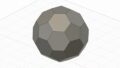
最後に全ボディを選択してステッチしてソリッド化すれば
![](https://i0.wp.com/tas400kt.xyz/wp-content/uploads/2021/05/022-3.jpg?resize=1024%2C582&ssl=1)
完成。
![](https://i0.wp.com/tas400kt.xyz/wp-content/uploads/2021/05/004-4.jpg?resize=1024%2C624&ssl=1)
↓以前に作った正多面体
コメント
[…] 3D-CAD遊び 正多面体作成-正12面体今回は正12面体を作ります。↓前回作っ… […]